We all know PVMs are the KINGs of this weird hobby. “OMG A SONY PVM”
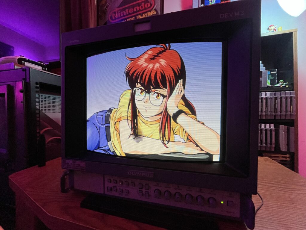
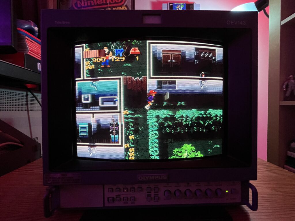
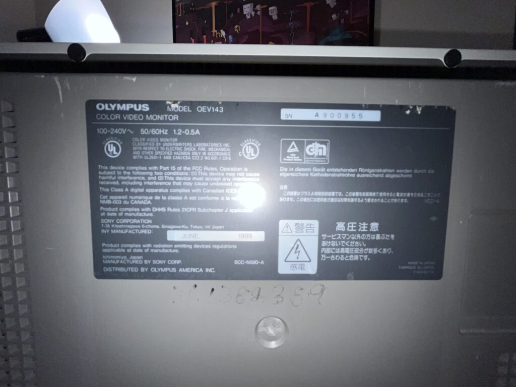
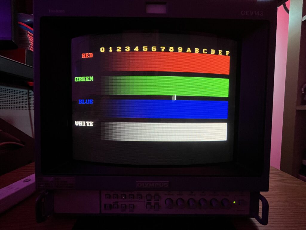
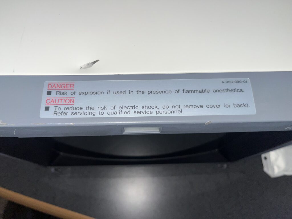
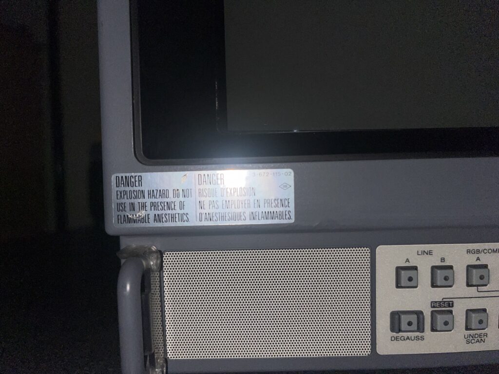
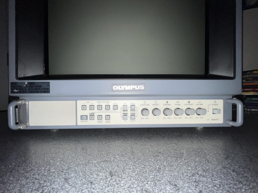
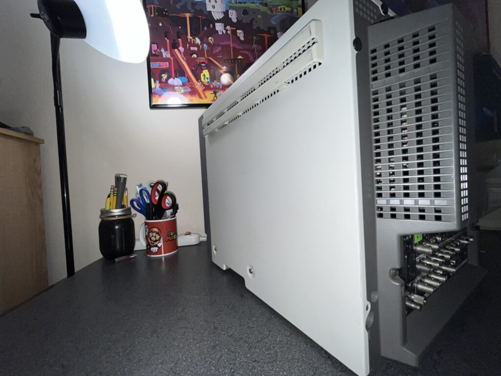
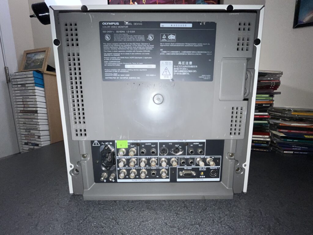
This one is a bit… different. PVMs and BVMs were for TV Studios, movie/video production and MUCH more. There is another market that requires surgically accurate images, literally. Surgical rooms. Imaging carts. Stuff that runs all day, every day, and cannot look like crap. Welcome to the Medical world of PVMs. This one sports an Olympus badge on the front but DO NOT let that fool you this is virtually identical to a Sony PVM-14M2MDU. It's legit a Sony PVM wearing scrubs and I just think she is so cool. This specific monitor of mine spent its entire life looking inside of people's Urinary Tracts……NEAT.
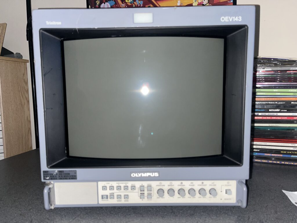
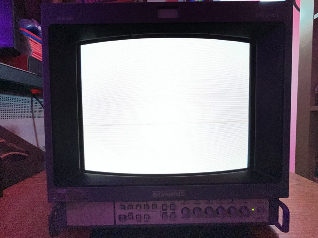
Condition?
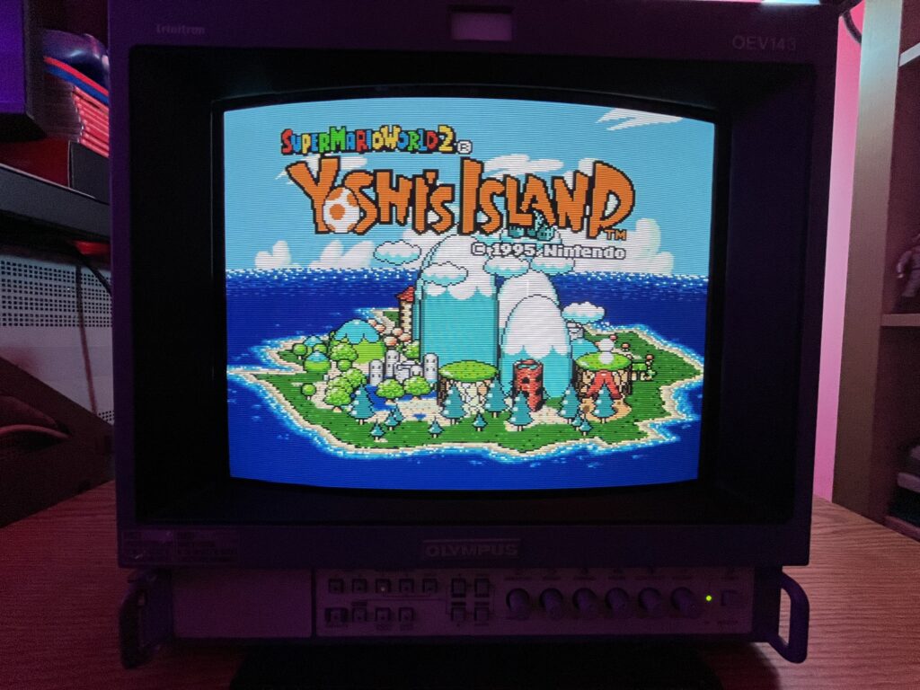
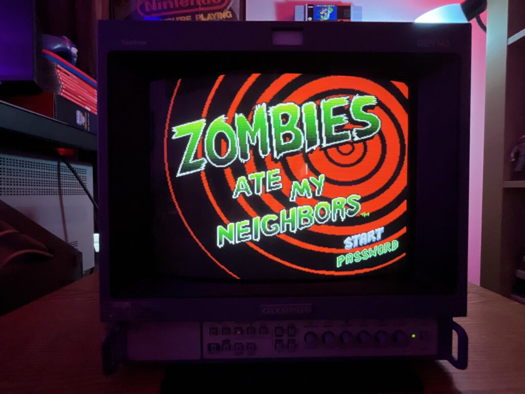
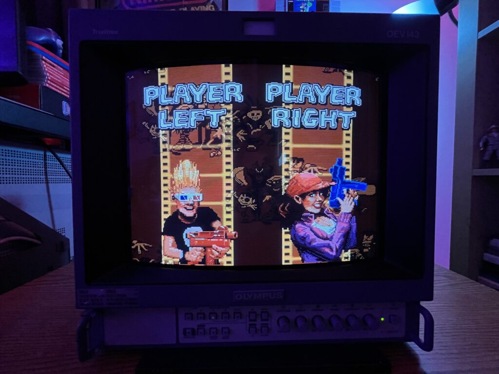
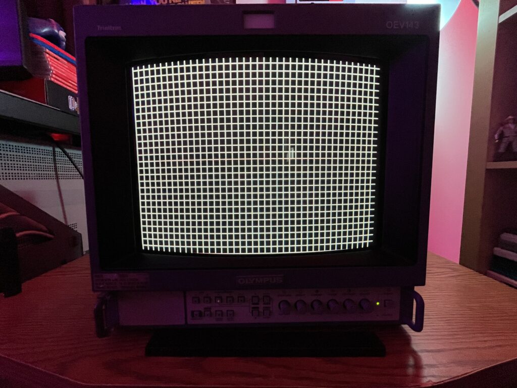
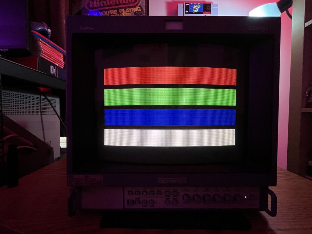
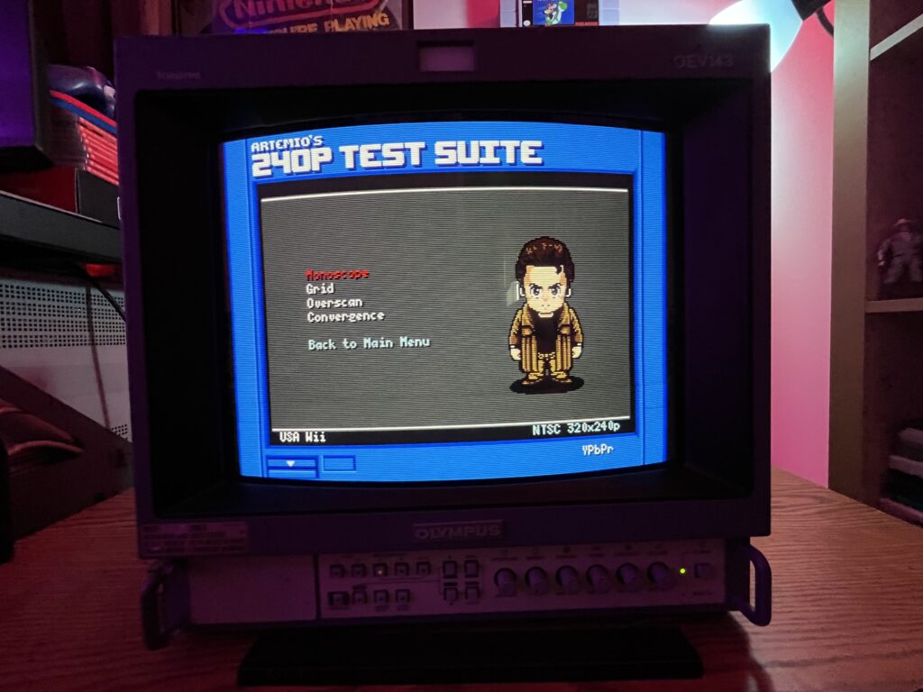
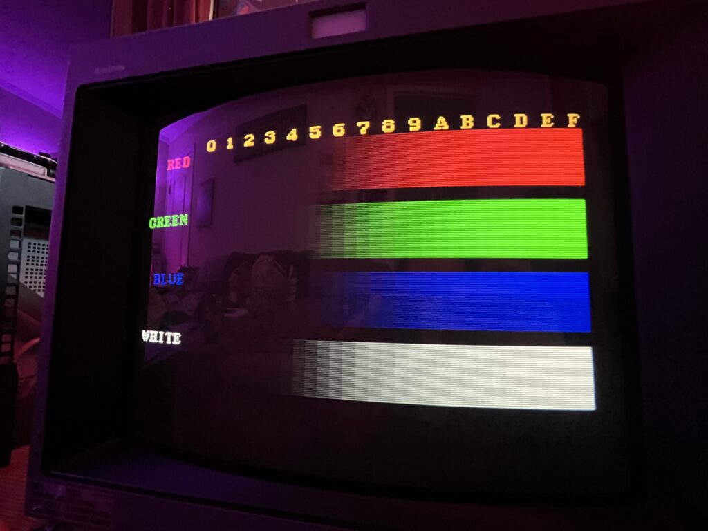
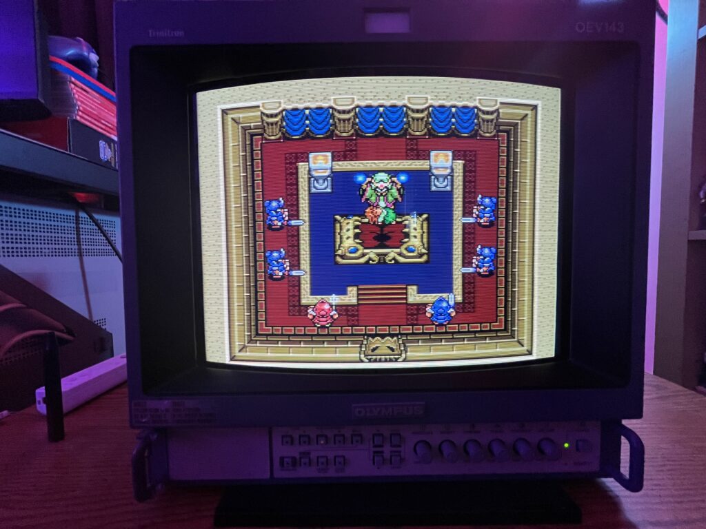
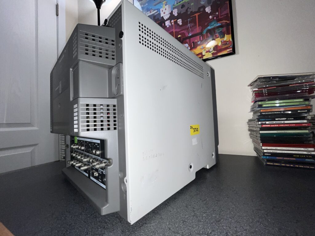
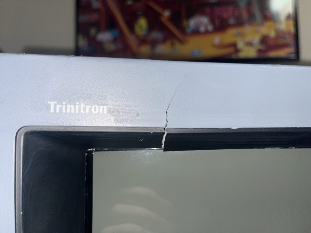
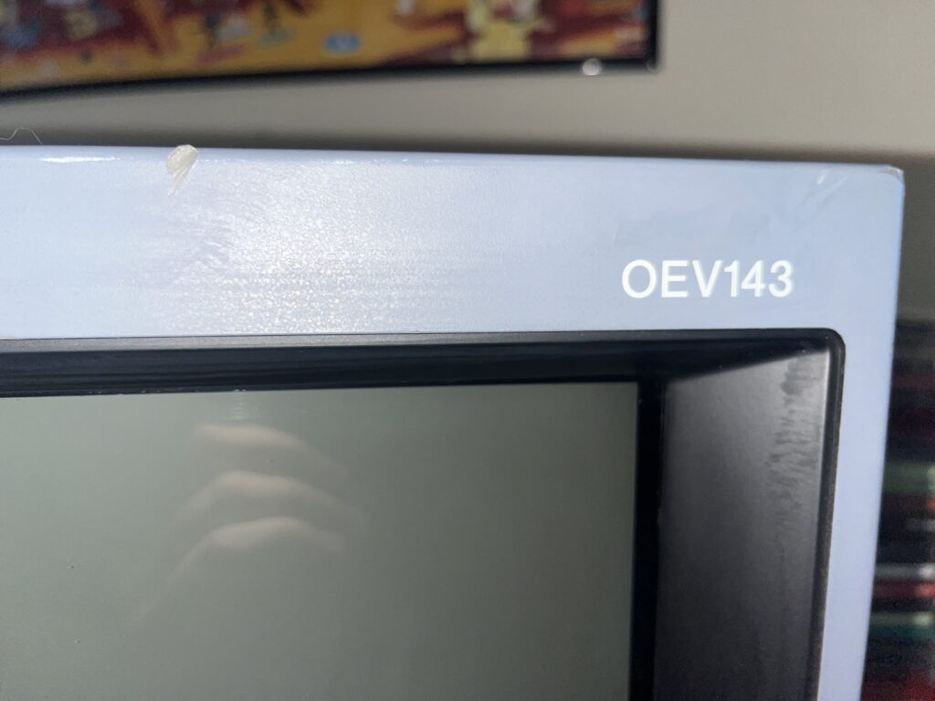
She is a bit beat up cosmetically but functionally she is absolutely mint. A small crack in the front bezel next to her iconic Trinitron logo and a nasty dent in the top of the metal case along with various scuffs and paint transfer/stains. The tube itself is perfect with zero scratches or marks on the screen. She is extremely bright, vibrant, and full of life. I did not touch a THING in the service menu so far. The images you see on this page are the first time I've tested her.
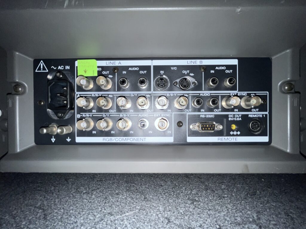
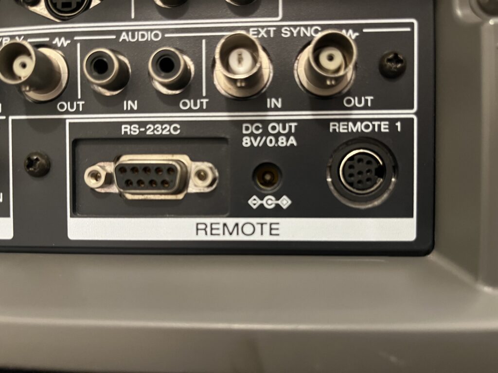
I got this tube from my.... CRT dealer. He suggests that she spent her life looking inside people's urinary tracts... I have a theory of how this tube was used. Skip all of the awesome features of this tube… I genuinely think this CRT spent its professional life in black and white! If you know anything about composite video you'll know that Composite = Y (luma) + C (chroma/color) mashed together. The ONLY input on the back of this monitor WITHOUT THICK DUST was the Y (luma) input of component. Y in component is traditionally a green cable. The Y signal carries brightness + sync only and it is literally the true black & white image from the source with full bandwidth → sharper detail, and cleaner edges. The color info of composite video kills this! Composite = Y (luma) + C (chroma/color) mashed together. Even if you think you’re looking at B&W, the color subcarrier (~3.58 MHz in NTSC) is still there. That leftover chroma causes: Dot crawl, Cross-color artifacts (fake colors in fine detail), Cross-luma artifacts (detail getting smeared) and The PVM/any TV has to separate luma from chroma, and that process is never perfect. Yes you can send black and white over composite BUT composite is like trying to listen to someone talk while music is playing on the same speaker and then filtering the voice back out. Y is just… the voice, clean and direct.
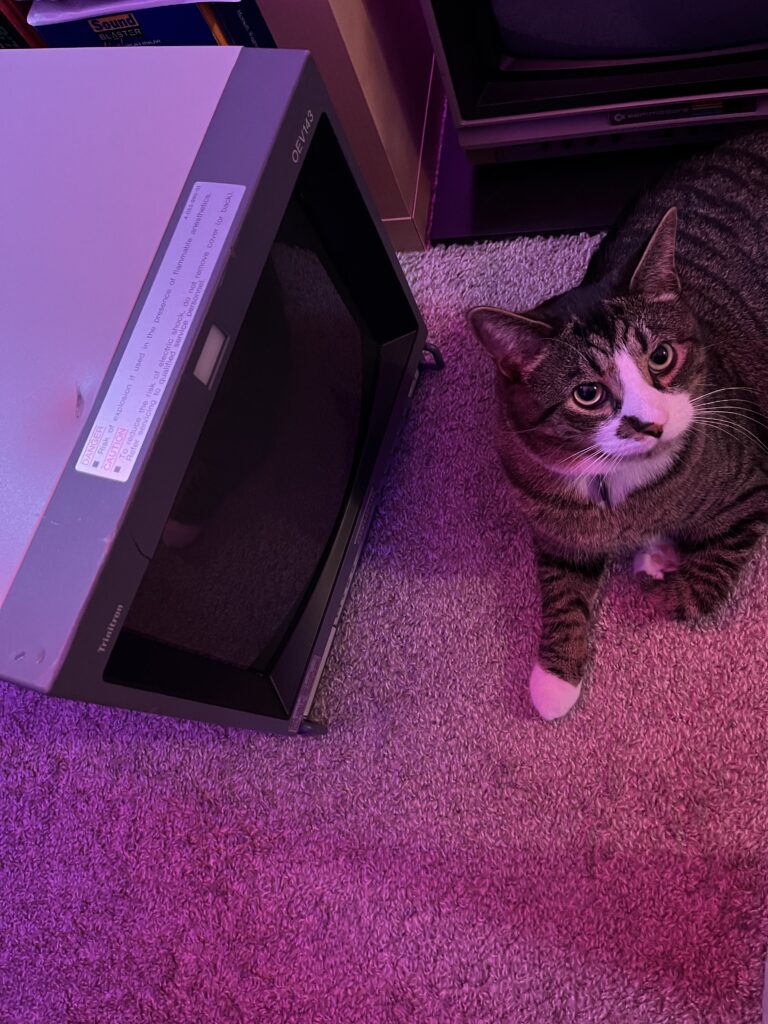
I think the camera used in these surgeries or…. the urinary tract stuff, was black and white kind of like what an ultrasound looks like…
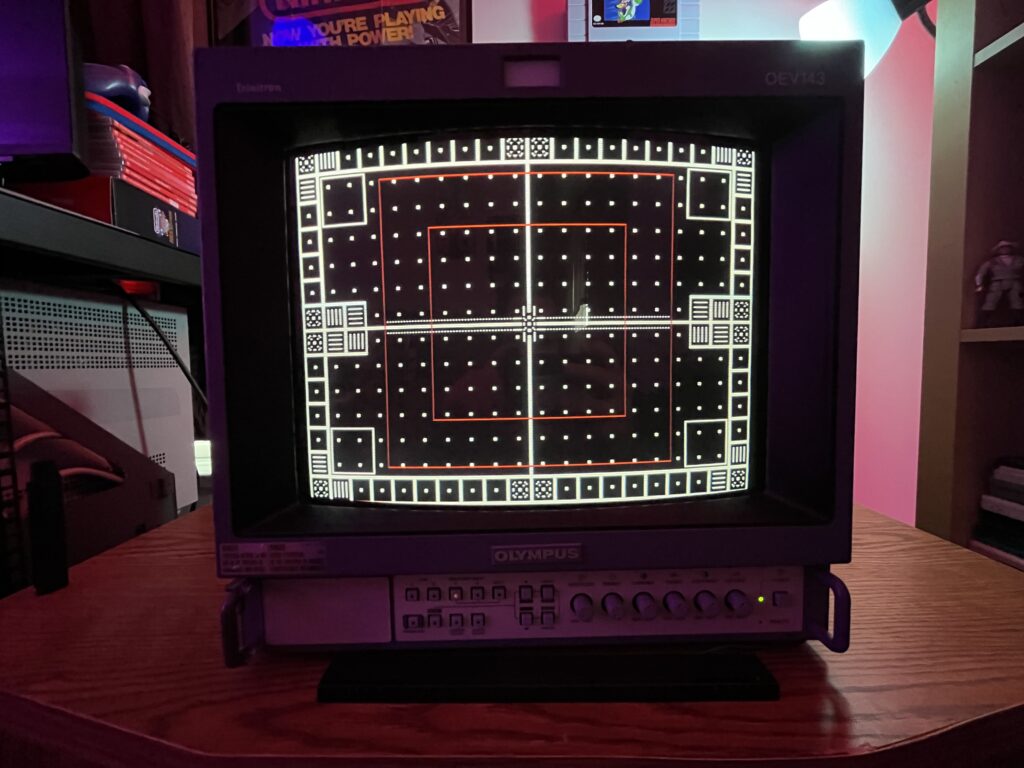
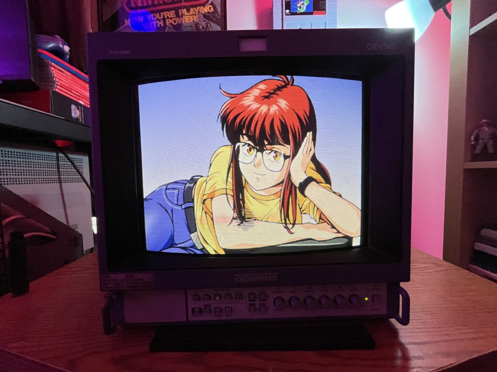
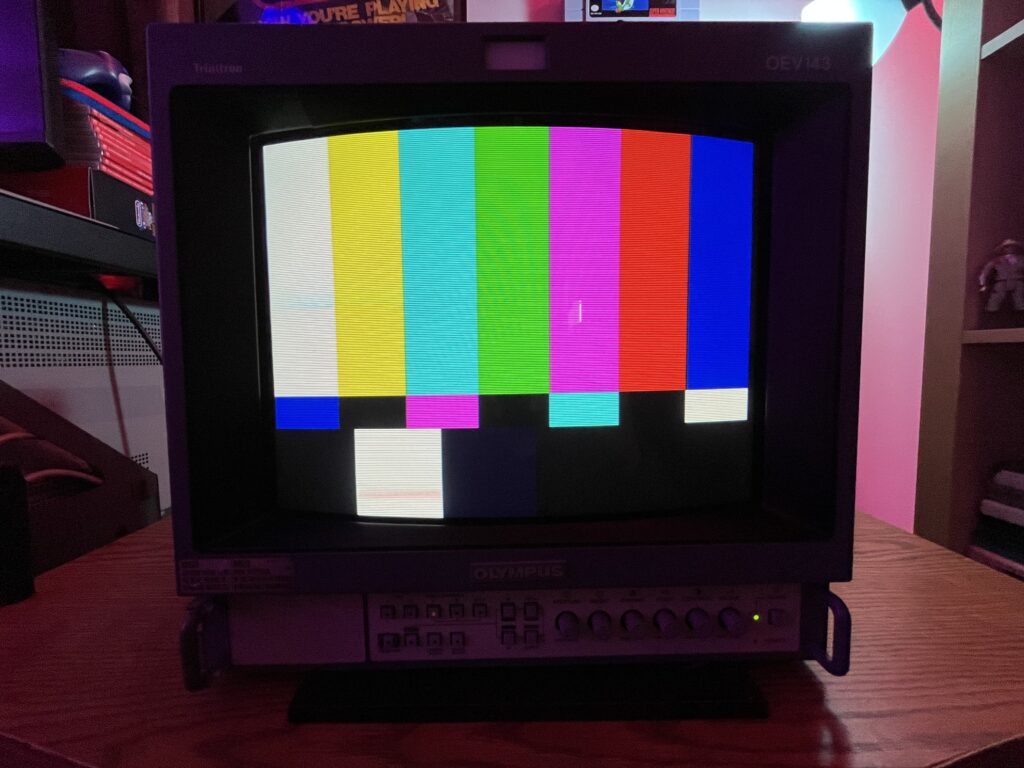
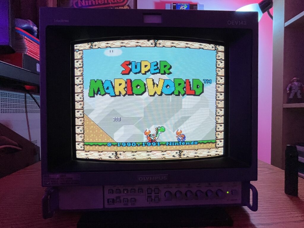
What's crazy is this is the one you actually want to play on compared to my 14M4U. Something about 600TVL is just somehow better than 800. Maybe I'm being silly but it just looks so much better for 240p gaming. The image just isn't being interrogated under a microscope but it's still such an obscene level of quality that just gives this tube a SOLID 9.4
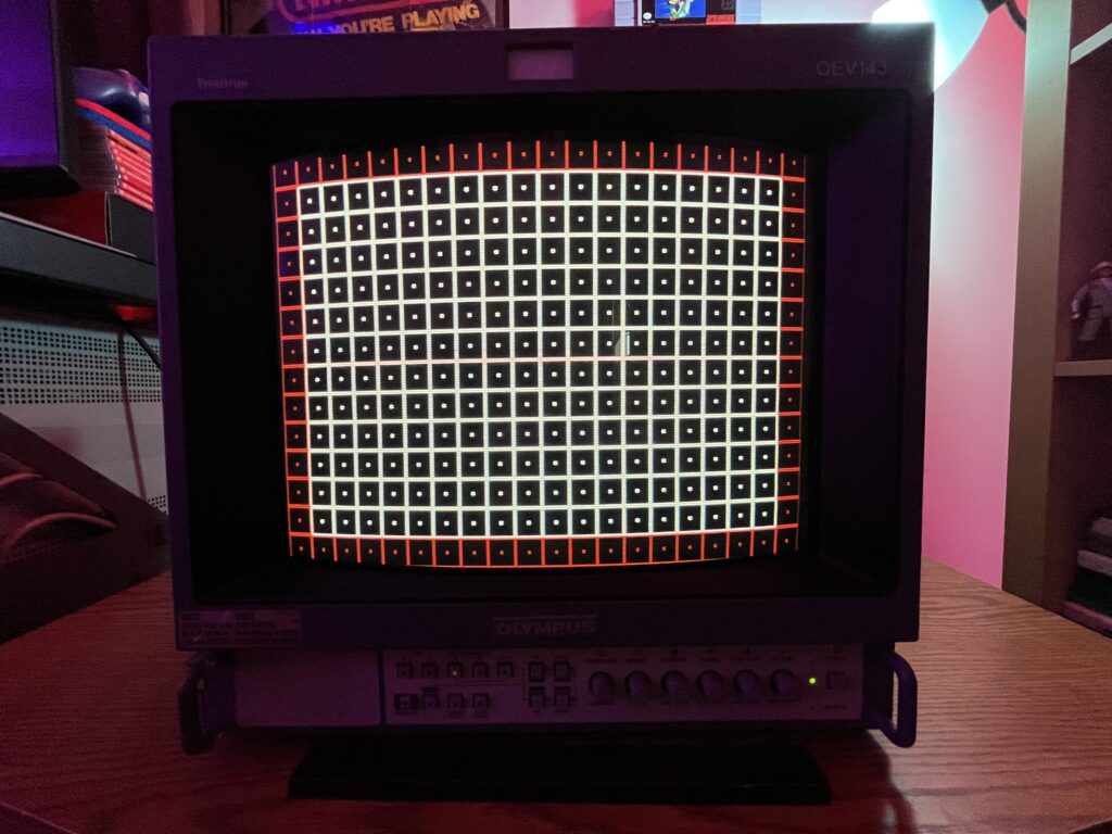
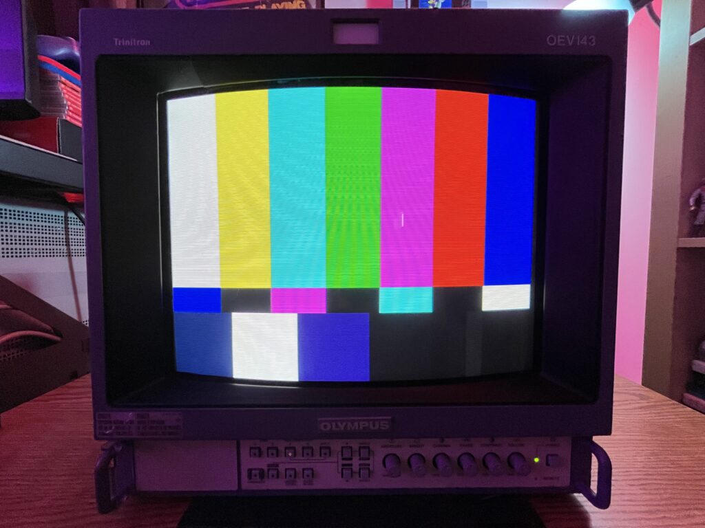
If the image shows bowing, tilt, uneven vertical spacing, or the raster is not centered, the cause is almost always in the deflection system or physical alignment rather than digital processing. The service manual confirms full geometry control through internal adjustment along with mechanical correction. The first step is entering service mode and correcting size, position, pincushion, trapezoid, and linearity electronically. If distortion remains after electrical adjustment, the issue is physical yoke alignment. The deflection yoke can shift slightly over time or from handling, causing horizontal bowing or skew. Correction involves loosening the yoke clamp and carefully rotating or repositioning it while monitoring a grid pattern. If geometry cannot be corrected cleanly, check for aging components in the horizontal/vertical deflection circuits, particularly electrolytic capacitors affecting waveform stability.
Vertical foldover / top line compression diagnosis
If the top portion of the image appears compressed, folded, or shows bright retrace lines, the issue is in the vertical deflection stage. This is typically caused by degraded electrolytic capacitors in the vertical output circuit, which affects the vertical ramp waveform. The service manual points to vertical amplitude and linearity adjustments, but when those cannot correct the issue, it becomes a component-level fault. The vertical output IC and surrounding capacitors are the primary suspects. Replacing the capacitors in that section usually restores full vertical scan. Continued operation in this state can stress the output IC.
Convergence error / color fringing diagnosis
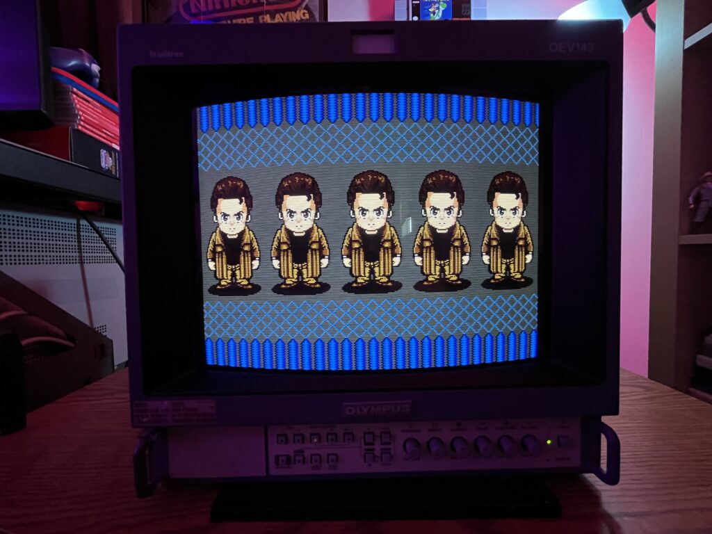
If red, green, and blue do not align, especially at edges or corners, this is convergence drift. The manual outlines static and dynamic convergence correction using internal magnets and rings on the neck of the tube. Minor issues are corrected through convergence strips or adjustments already present on the tube assembly. Larger errors indicate that the tube has shifted slightly or has been impacted. Electrical convergence adjustments are limited on this chassis, so most correction is physical. If convergence cannot be corrected across the entire screen, the tube may have age-related drift or mechanical misalignment that cannot be fully eliminated.
Soft focus / edge blur diagnosis
If the image is sharp in the center but blurry toward edges, or overall focus is weak, the issue lies in the focus and high voltage system. The flyback transformer contains focus and screen controls which are adjusted manually. The service procedure specifies setting G2 (screen voltage) first, then adjusting focus for best clarity. If proper adjustment cannot achieve a sharp image, the tube itself may be worn, or the focus divider inside the flyback may be degrading. Edge softness is normal to a degree on Trinitrons, but excessive blur indicates aging components or misadjustment.
Brightness imbalance / gray scale drift diagnosis
If whites are tinted or grayscale is not neutral, the issue is improper bias and gain settings for each color channel. The service manual defines white balance calibration using cutoff and drive adjustments for red, green, and blue. This must be done using a proper test pattern and controlled input signal. If one color is weak even after adjustment, it may indicate uneven gun wear in the CRT. If colors fluctuate or drift over time, suspect aging capacitors in the video amplifier stages or unstable power regulation.
No sync / rolling image diagnosis
If the image rolls vertically or horizontally or cannot lock, the sync system is not properly receiving or processing the sync signal. This monitor supports both internal sync (composite video) and external sync via BNC. Incorrect input configuration or missing sync signal will cause instability. The manual specifies checking EXT SYNC input and termination. If sync is present but unstable, the issue may be in the sync separator circuit or related processing ICs. Poor cables or improper termination can also cause this behavior.
No image / raster present diagnosis
If the screen lights up but no image is visible, the issue is likely in the video signal path rather than the CRT itself. The presence of raster confirms high voltage and deflection are working. Check input selection, signal routing, and input boards. The manual outlines signal flow through input stages, and failure in these circuits can result in blank video. If no raster at all is present, the issue is more serious and involves the power supply or high voltage section. Power issues / intermittent startup diagnosis
If the unit fails to power on or shuts down intermittently, the power supply section is the primary suspect. The manual includes voltage checkpoints that should be verified. Aging capacitors in the power supply can cause unstable operation or failure to start. Cold solder joints are also common in older units and can cause intermittent faults. If the unit clicks or attempts to start repeatedly, it may be entering protection due to overcurrent or voltage faults.
Color purity issues / discoloration diagnosis
If areas of the screen show incorrect color tinting, especially in corners, the issue is magnetic interference or purity misalignment. The built-in degauss circuit should correct minor issues on power-up. If not, manual degaussing is required. Persistent purity problems may require adjustment of the purity rings on the tube. External magnetic sources such as speakers or transformers can also cause this and should be removed before attempting correction.
Portions of this page include archived materials, images, and reference content originally published by Olympus. These assets were sourced from publicly available historical snapshots via the Internet Archive and are used for informational, educational, and preservation purposes only.

All trademarks, logos, and original materials remain the property of their respective owners. This site is an independent archival project and is not affiliated with or endorsed by Olympus. If you are a rights holder and would like any material removed or credited differently, please contact me and I will address it promptly.